Hardware
- Rundes 1,28-Zoll-IPS-LCD-Display
- RP Pico 2040 (inclusive)
- USB-A zu USB-C Kabel
![]()
Da Waveshare keine Beispiele in CircuitPython bereitstellt, gab es zunächst auch nur unter Micropython einen Treiber für den ACC-Sensor
beim runden LCD Display. Und unter CircuitPython arbeitete der natürlich nicht. Daher habe ich meine Bemühungen darauf gerichtet,
diesen Treiber 'QMI8658' auf CircuitPython anzupassen.
Es ist so weit. Der Treiber 'QMI8658' zum Auslesen der Sensorwerte beim runden Pico-LCD-Display mit der Firmware 'CircuitPython' ist fertig.
Der eingebaute Sensor ermöglicht die Messung der Beschleunigung in 3 Achsen (3-Achsen-Beschleunigungsmesser) und der Orientierung in
3 Achsen (3 Achsen-Gyroskop). Die Bibliothek heißt bei mir 'my_qmi8658.py'. Sie liest die Werte über den
I2C-Bus aus und man kann sie weiterverarbeiten. Ich stelle die Bibliothek unter Haftungsausschluss zur freien Nutzung zur Verfügung und
erwarte, dass der Urheberhinweis nicht entfernt wird.
Los gehts
Die Bibliothek können Sie als zip-Datei
hier herunterladen
, entpacken und in den lib-Ordner ihres 'CIRCUITPY'-Laufwerkes kopieren.
Im unteren Kasten sehen Sie den gesamten Quelltext:
1   # SPDX-FileCopyrightText: 2023 Detlef Gebhardt, written for CircuitPython
2   # SPDX-FileCopyrightText: Copyright (c) 2023 Detlef Gebhardt
3   # SPDX-FileCopyrightText: based on a Waveshare template in Micropython
4   #
5   # SPDX-License-Identifier: GEBMEDIA
6   import board
7   import busio
8   import time
9
10  i2c_sda = board.GP6
11  i2c_sdl = board.GP7
12  dc = board.GP8
13  cs = board.GP9
14  sck = board.GP10
15  mosi = board.GP11
16  rst = board.GP12
17  bl = board.GP25
18
19  class QMI8658:
20      def __init__(self, address=0x6B):
21          self._address = address
22          self._bus = busio.I2C(scl=i2c_sdl, sda=i2c_sda, frequency=100_000)
23          bRet = self.WhoAmI()
24          if bRet:
25              self.Read_Revision()
26          else:
27              return None
28          self.Config_apply()
29
30      def _read_byte(self, cmd):
31          while not self._bus.try_lock():
32              pass
33          rec = bytearray(1)
34          self._bus.readfrom_into(self._address, rec, start=cmd)
35          return rec[0]
36
37      def _read_block(self, reg, length=1):
38          rec = bytearray(length)
39          self._bus.writeto(0x6b, bytes([reg]))
40          self._bus.readfrom_into(self._address, rec)
41          return rec
42
43      #def _read_u16(self, cmd):
44      #    rec = bytearray(2)
45      #    self._bus.readfrom_into(self._address, rec, start=cmd)
46      #    return (rec[1] << 8) + rec[0]
47
48      #def _write_byte(self, cmd, val):
49      #    self._bus.writeto(self._address, bytes([cmd, val]))
50
51      def WhoAmI(self):
52          bRet = False
53          while not self._bus.try_lock():
54              pass
55          self._bus.writeto(0x6b, bytes([0x05]))
56          result = bytearray(2)
57          self._bus.readfrom_into(0x6b, result)
58          if result == bytearray(b'\x00\x00'):
59              bRet = True
60          return bRet
61
62      def Read_Revision(self):
63          self._bus.writeto(0x6b, bytes([0x01]))
64          result = bytearray(2)
65          self._bus.readfrom_into(0x6b, result)
66          return result
67
68      def Config_apply(self):
69          # REG CTRL1
70          self._bus.writeto(0x6b, bytes([0x02, 0x60]))
71          result = bytearray(4)
72          self._bus.readfrom_into(0x6b, result)
73          # REG CTRL2 : QMI8658AccRange_8g  and QMI8658AccOdr_1000Hz
74          self._bus.writeto(0x6b, bytes([0x03, 0x23]))
75          result = bytearray(4)
76          self._bus.readfrom_into(0x6b, result)
77          # REG CTRL3 : QMI8658GyrRange_512dps and QMI8658GyrOdr_1000Hz
78          self._bus.writeto(0x6b, bytes([0x04, 0x53]))
79          result = bytearray(4)
80          self._bus.readfrom_into(0x6b, result)
81          # REG CTRL4 : No
82          self._bus.writeto(0x6b, bytes([0x05, 0x00]))
83          result = bytearray(4)
84          self._bus.readfrom_into(0x6b, result)
85          # REG CTRL5 : Enable Gyroscope And Accelerometer Low-Pass Filter
86          self._bus.writeto(0x6b, bytes([0x06, 0x11]))
87          result = bytearray(4)
88          self._bus.readfrom_into(0x6b, result)
89          # REG CTRL6 : Disables Motion on Demand.
90          self._bus.writeto(0x6b, bytes([0x07, 0x00]))
91          result = bytearray(4)
92          self._bus.readfrom_into(0x6b, result)
93          # REG CTRL7 : Enable Gyroscope And Accelerometer
94          self._bus.writeto(0x6b, bytes([0x08, 0x03]))
95          result = bytearray(4)
96          self._bus.readfrom_into(0x6b, result)
97
98      def Read_Raw_XYZ(self):
99          xyz = [0, 0, 0, 0, 0, 0]
100         raw_timestamp = self._read_block(0x30, 3)
101         raw_acc_xyz = self._read_block(0x35, 12)
102         raw_gyro_xyz = self._read_block(0x3b, 12)
103         raw_xyz = self._read_block(0x35, 12)
104        timestamp = (raw_timestamp[2] << 16) | (raw_timestamp[1] << 8) | (raw_timestamp[0])
105         for i in range(6):
106            # xyz[i]=(raw_acc_xyz[(i*2)+1]<<8)|(raw_acc_xyz[i*2])
107            # xyz[i+3]=(raw_gyro_xyz[((i+3)*2)+1]<<8)|(raw_gyro_xyz[(i+3)*2])
108            xyz[i] = (raw_xyz[(i * 2) + 1] << 8) | (raw_xyz[i * 2])
109            if xyz[i] >= 32767:
110                 xyz[i] = xyz[i] - 65535
111         return xyz
112
113     def Read_XYZ(self):
114         xyz = [0, 0, 0, 0, 0, 0]
115         raw_xyz = self.Read_Raw_XYZ()
116         # QMI8658AccRange_8g
117         acc_lsb_div = 1 << 12
118         # QMI8658GyrRange_512dps
118         gyro_lsb_div = 64
120         for i in range(3):
121             xyz[i] = raw_xyz[i] / acc_lsb_div  # (acc_lsb_div/1000.0)
122             xyz[i + 3] = raw_xyz[i + 3] * 1.0 / gyro_lsb_div
123         return xyz
124
125 if __name__=='__main__':
126    # do nothing
127    pass
Die Zeile 125 bis 127 sorgen dafür, dass die Datei erwartet, als Modul importiert zu werden. Deshalb passiert beim Starten in Thonny nichts. Ein Programm, welches also die Sensorwerte benutzen soll, muss deshalb wie folgt aufgebaut sein:
1  import time
2  import board
3  import my_qmi8658
4
5
6  # acc initialisieren
7  sensor=my_qmi8658.QMI8658()
8
9  while True:
10     xyz=sensor.Read_XYZ()
11     # Display wird rel. zur x-Achse bewegt
12     wert_x = (10)*xyz[3]
13     wert_y = (10)*xyz[4]
14     wert_z = (10)*xyz[5]
15     print(wert_x,",",wert_y,",",wert_z)
16     time.sleep(0.1)
- In Zeile 3 wird die Bibliothek importiert. Dazu muss sie im lib-Ordner vorhanden sein.
- Zeile 7 initialisiert den Sensor, d.h. der Variable 'sensor' wird aus der Bibliothek 'my_qmi8658' die
'class QMI8658' zugewiesen.
- In der 'while'-Schleife wird in Zeile 10 die Funktion 'Read_XYZ()' aufgerufen, welche die Werte liest. Danach erfogt in den Zeilen 12,
13 und 14 die Zuweisung zu 'wert_x', 'wert_y' und 'wert_z', um sie in der Konsole zu drucken.
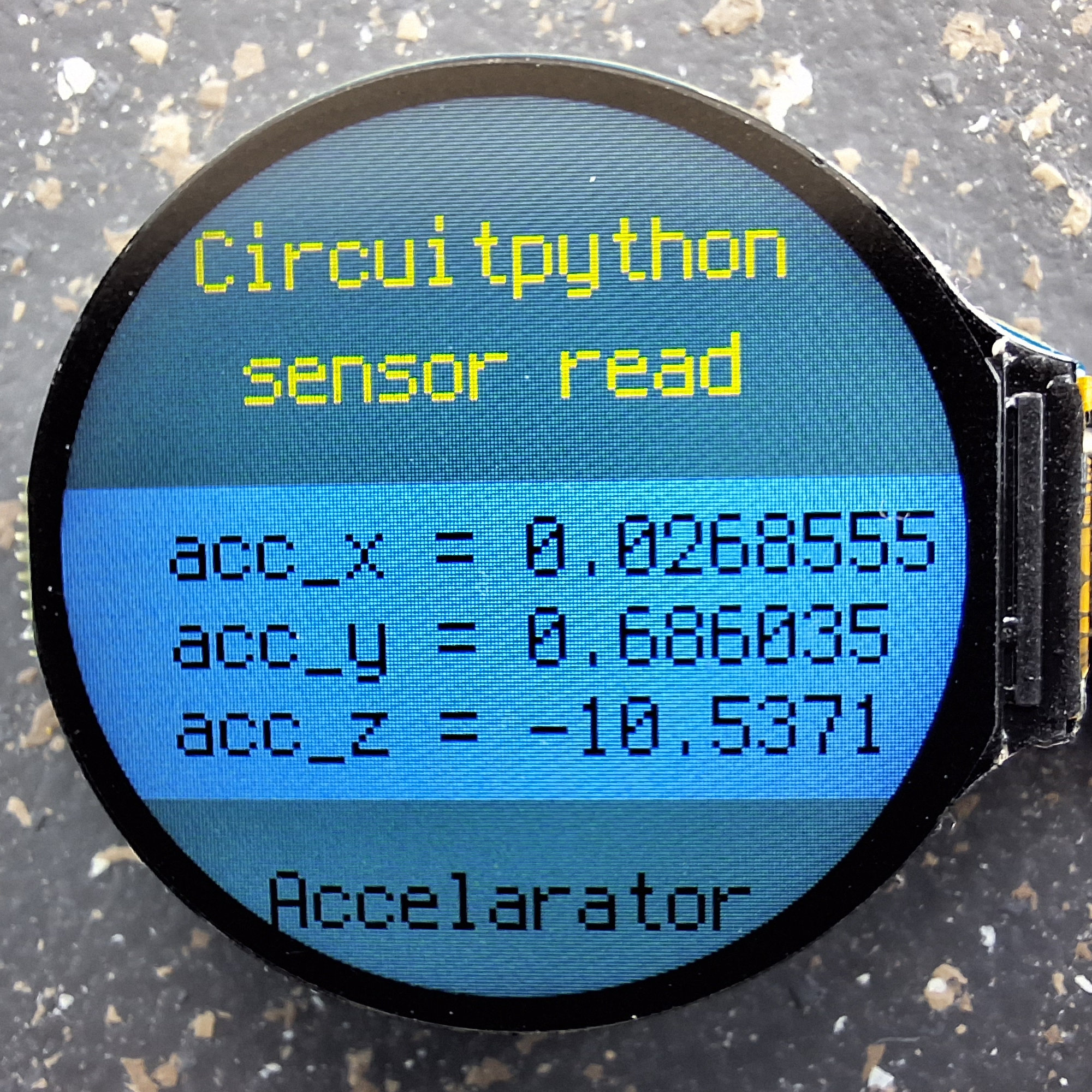
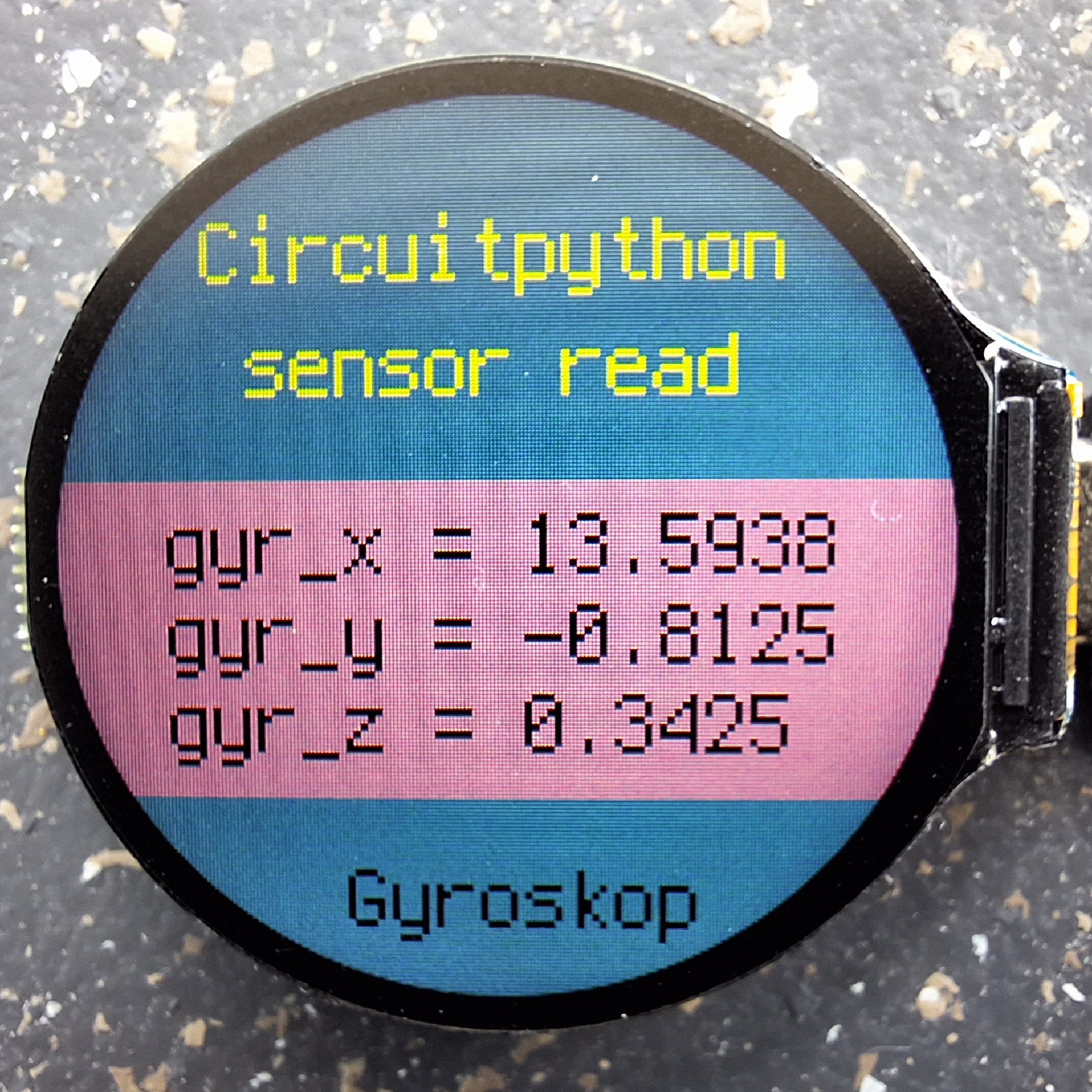
Bewegen Sie das Display, sehen Sie, wie sich die Werte verändern. Damit ist eine erste Funktionsprobe möglich. Mit der grundsätzlich
gleichen Funktionalität ist auch das Beispielprogramm auf den Fotos oben in der Box ausgestattet. Hier ist die Anzeige auf dem Display
nur etwas 'aufgehübscht'. Probieren Sie es aus.
1   import time
2   import board
3   import busio
4   import displayio
5   import terminalio
6   import fourwire
7   import gc9a01
8   import my_qmi8658
9   from adafruit_display_text import label
10  from adafruit_ticks import ticks_ms
11  from adafruit_display_shapes.rect import Rect
12
13  # Release any resources currently in use for the displays
14  displayio.release_displays()
15
16  # Make the displayio SPI bus and the GC9A01 display
17  spi = busio.SPI(clock=board.GP10, MOSI=board.GP11)
18  display_bus = fourwire.FourWire(spi, command=board.GP8, chip_select=board.GP9, reset=board.GP12)
19  display = gc9a01.GC9A01(display_bus, width=240, height=240, rotation=90, backlight_pin=board.GP25)
20
21  # acc initialisieren
22  sensor=my_qmi8658.QMI8658()
23
24  acc_x = "0"
25  acc_y = "0"
26  acc_z = "0"
27
28  # Make the display context
29  main = displayio.Group()
30  display.root_group = main
31
32  # make bitmap that spans entire display, with 2 colors
33  background = displayio.Bitmap(240, 190, 1)
34  # make a 2 color palette to match
35  mypal = displayio.Palette(3)
36  mypal[0] = 0xff9999
37  mypal[1] = 0x03c2fc
38  background.fill(1)
39  # Put background into main group, using palette to map palette ids to colors
40  main.append(displayio.TileGrid(background, pixel_shader=mypal))
41
42  background2 = Rect(0,0, 240, 100, fill=0x009999 )
43  main.append(background2)
44  background3 = Rect(0,185, 240, 60, fill=0x009999 )
45  main.append(background3)
46
47  text_group_t1 = displayio.Group(scale=2, x=40, y=40)
48  text1 = "Circuitpython\n sensor read"
49  text_area1 = label.Label(terminalio.FONT, text=text1, color=0xffff00)
50  text_group_t1.append(text_area1)
51  main.append(text_group_t1)
52
53  ## create the label for sensors
54  updating_label1 = label.Label(font=terminalio.FONT, text="", scale=2, color=0x000000, line_spacing=1)
55  # set label position on the display and add label
56  updating_label1.anchor_point = (0, 0)
57  updating_label1.anchored_position = (30, 105)
58  main.append(updating_label1)
59
60  view=0
61  start = ticks_ms()
62
63  while True:
64      xyz=sensor.Read_XYZ()
65      # Display wird rel. zur x-Achse bewegt
66      acc_x = (10)*xyz[0]
67      acc_y = (10)*xyz[1]
68      acc_z = (10)*xyz[2]
69      gyr_x = (2)*xyz[3]
70      gyr_y = (2)*xyz[4]
71      gyr_z = (2)*xyz[5]
72      if view == 0:
73          background.fill(1)
74          sensorwerte = "acc_x = "+str(acc_x)+"\nacc_y = "+str(acc_y)+"\nacc_z = "+str(acc_z)+ "\n\n  Accelarator"
75      else:
76          background.fill(0)
77          sensorwerte = "gyr_x = "+str(gyr_x)+"\ngyr_y = "+str(gyr_y)+"\ngyr_z = "+str(gyr_z)+ "\n\n    Gyroskop"
78      if view == 0 and (ticks_ms() - start)/ 1000 > 10:
79          view = 1
80          start = ticks_ms()
81      if view == 1 and (ticks_ms() - start)/ 1000 > 10:
82          view = 0
83          start = ticks_ms()
84      updating_label1.text = sensorwerte
85      time.sleep(0.1)
Die Lücke mit dem fehlenden Treiber ist jetzt geschlossen. Probieren Sie ein wenig mit dem Programm herum und
lernen dabei das Display kennen. Genau das war das Anliegen dieser Anleitung.
Viel Spass und Erfolg beim Ausprobieren.
Viel Spass und Erfolg beim Ausprobieren.