Ein wenig Mathematik muss sein:
- kleiner Exkurs in die Winkelfunktionen -
Bildbox 1 (klick hier)
Ein wenig Mathematik muss sein:
- kleiner Exkurs in die Winkelfunktionen -
![]()
Bildbox 1 (klick hier)
Hardware
- Rundes 1,28-Zoll-IPS-LCD-Display RP Pico 2040 oder
- Rundes 1,28-Zoll-IPS-LCD-Display RP Pico 2350
- USB-A zu USB-C Kabel
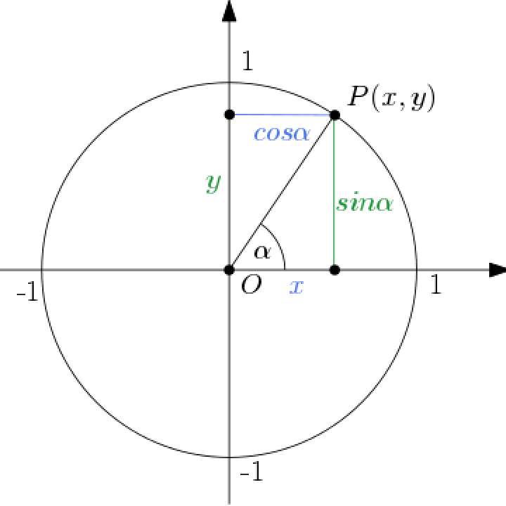
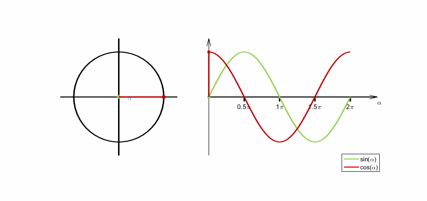
Unser Display ist rund. Deshalb kommt man z.B. bei der Darstellung von Punkten, Zeigern u.ä. nicht ohne die Winkelfunktionen Sinus und Cosinus
aus. Gehen wir kurz auf die Definitionen von Sinus und Cosinus ein.
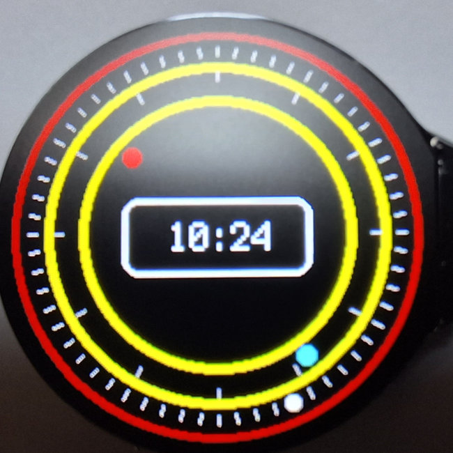
Auf den beiden unteren Fotos wird das für die 'Sekundenpunkte', 'Minutenpunkte', 'Stundenpunkte' bzw. die Position der Zeigerspitzen genuzt.
Los gehts mit einem Beispiel
(Verwenden Sie als Bibliotheken im 'lib-Ordner' die selben, wie in der Anleitung 'verbesserte Analoguhr' hier .)
Das Display hat 240 x 240 Pixel. Der Mittelpunkt liegt also bei P(120/120), so dass wir als Koordinaten nachfolgend immer xpos = 120 und ypos = 120 nutzen.
Die jeweils neue x-Koordinate ergibt sich dann aus
Da 2*pi bekanntlich 360 Grad entsprechen, lassen sich mit pi/30 die 60 'Positionen' (360 / 180 * 30 = 60) darstellen. Mit der 100 wird in unserem Fall der Radius festgelegt. Hier nun das Beispielprogramm:
1  # SPDX-FileCopyrightText: 2023 Detlef Gebhardt, written for CircuitPython
2  # SPDX-FileCopyrightText: Copyright (c) 2023 Detlef Gebhardt
3  #
4  # SPDX-License-Identifier: GEBMEDIA
5  import time
6  import gc
7  import board
8  import busio
9  from busio import I2C
10 import displayio
11 import terminalio
12 import gc9a01
13 from adafruit_display_text import label
14 from adafruit_display_shapes.circle import Circle
15 import random
16 import math
17 import fourwire
18 # Release any resources currently in use for the displays
19 displayio.release_displays()
20
21 # Make the displayio SPI bus and the GC9A01 display
22 spi = busio.SPI(clock=board.GP10, MOSI=board.GP11)
23 display_bus = fourwire.FourWire(spi, command=board.GP8, chip_select=board.GP9, reset=board.GP12)
24 display = gc9a01.GC9A01(display_bus, width=240, height=240, backlight_pin=board.GP25)
25
26 # Make the display context
27 group1 = displayio.Group()
28 display.root_group = group1
29
30 width = 240
31 height = 240
32 xpos = 120
33 ypos = 120
34 radius = 120
35 i = 0
36
37# Make some circle:
38 circle = Circle(xpos, ypos, 120, fill=0xff0000, outline=0x000000)
39 group1.append(circle)
40 circle = Circle(xpos, ypos, 115, fill=0x000000, outline=0x000000)
41 group1.append(circle)
42 circle = Circle(xpos, ypos, 85, fill=0xffff00, outline=0xffff00)
43 group1.append(circle)
44 circle = Circle(xpos, ypos, 10, fill=0x0000ff, outline=0xffff00)
45 group1.append(circle)
46
47 while True:
48     for i in range (60):
49         xpos_neu = int(width/2 + 100*math.cos((i -15)*math.pi/30))
50         delta_x = xpos_neu - xpos
51         xpos = xpos_neu
52         ypos_neu = int(height/2 + 100*math.sin((i -15)*math.pi/30))
53         delta_y = ypos_neu - ypos
54         ypos = ypos_neu
55         circle.x = circle.x + delta_x
56         circle.y = circle.y + delta_y
57         time.sleep(0.05)
58         gc.collect()
59    #print(gc.mem_free())
Ein paar Erläuterungen. Die Programmzeilen 5 bis 28 entsprechen dem vorigen Beitrag zur Initialisierung des
Displays. Hinzu gekommen sind die Module 'from adafruit_display_shapes.circle import Circle' und
'import math', welche für die Kreisdarstellung und die mathematischen Berechnungen gebraucht
werden. In den Zeilen 37 bis 45 werden Kreise dargestellt, welche nacheinander das Display rot, dann mit kleinerem Durchmesser
schwarz und schließlich gelb einfärben. Zuletzt wird ein kleiner blauer Kreis als Punkt in dem schwarzen Ring
dargestellt. Sie sehen, dass die Syntax für den Kreis immer
circle = Circle(xpos, ypos, radius, fillcolor, outlinecolor)
ist. Es folgt die 'while' Schleife in Zeile 47. Dort wird in den Zeilen 56 und 57 eine Eigenschaft bei 'circle' genutzt, welche
mit 'circle.x' bzw. 'circle.y' die neue x und y Position des Mittelpunktes annehmen kann, ohne den Kreis neu definieren zu
müssen. Stattdessen wird in den Zeilen 49 bis 54 der neue geänderte Wert berechnet und als 'delta_x' und 'delta_y' zu
den Mittelpunktkoordinaten addiert. Dass hat den riesigen Vorteil, dass kein zusätzlicher Speicher belegt wird, denn dann
würde ganz schnell ein 'MemoryError' das Programm beenden.
Ich habe das Ganze in eine 'for i in range (60)' Schleife gepackt, deshalb steht in Zeile 49 und 52 beim Sinus bzw. Cosinus das 'i'.
Die subtrahierte 15 hat ihren Sinn, weil ich das Display bei der Initialisierung um 90 Grad gedreht habe (siehe Zeile 24) und die
Bewegung oben beginnen soll. Experimentieren Sie mit dem Beispiel und demnächst geht es weiter.
Zuvor gibt es aber noch eine kleine Zugabe. Probieren Sie das folgende Programm aus.
Zum Zeitpunkt als diese Seite erstellt wurde, war der Treiber für den ACC-Sensor unter CircuitPython noch
nicht fertig. Deshalb wurde mit Hilfe der Zufallsfunktion 'random' ein 'wert = random.randint(min,max)' als ganzzahliger
Zufallswert zwischen 'min' und 'max' erzeugt. Dieser wurde für die x- und y-Koordinaten verwendet, so dass der Punkt hin- und
hersprang, bis er den weißen Punkt traf.
1   # SPDX-FileCopyrightText: 2023 Detlef Gebhardt, written for CircuitPython
2   # SPDX-FileCopyrightText: Copyright (c) 2023 Detlef Gebhardt
3   #
4   # SPDX-License-Identifier: GEBMEDIA
5   import time
6   import gc
7   import board
8   import busio
9   from busio import I2C
10  import displayio
11  import terminalio
12  import gc9a01
13  import my_qmi8658
14  from adafruit_display_text import label
15  from adafruit_display_shapes.circle import Circle
16  import random
17  import fourwire
18  # Release any resources currently in use for the displays
19  displayio.release_displays()
20
21  # Make the displayio SPI bus and the GC9A01 display
22  spi = busio.SPI(clock=board.GP10, MOSI=board.GP11)
23  display_bus = fourwire.FourWire(spi, command=board.GP8, chip_select=board.GP9, reset=board.GP12)
24  display = gc9a01.GC9A01(display_bus, width=240, height=240, backlight_pin=board.GP25)
25
26  # Make the display context
27  group1 = displayio.Group()
28  display.root_group = group1
29
30  # acc initialisieren
31  sensor=my_qmi8658.QMI8658()
32
33  width = 240
34  height = 240
35  xpos = 120
36  ypos = 120
37  radius = 120
38  xpos_neu = 0
39  ypos_neu = 0
40
41  # Make some circle:
42  circle = Circle(xpos, ypos, 120, fill=0xff0000, outline=0x000000)
43  group1.append(circle)
44  circle = Circle(xpos, ypos, 110, fill=0x000000, outline=0x000000)
45  group1.append(circle)
46  circle_m = Circle(xpos, ypos, 16, fill=0xffffff, outline=0x000000)
47  group1.append(circle_m)
48  circle_p = Circle(xpos, ypos, 10, fill=0x0000ff, outline=0xffff00)
49  group1.append(circle_p)
50
51  while True:
52      #read QMI8658
53      val=sensor.Read_XYZ()
54      # Display wird rel. zur x-Achse bewegt
55      wert_x = (100)*val[0]
56      # Display wird rel. zur y-Achse bewegt
57      wert_y = (50)*val[1]
58      # x-Werte
59      ## Ausschlag nach rechts
60      if wert_x < 0 and wert_x >= -10:
61          x = +5
62      # Ausschlag nach links
63      if wert_x >= 0 and wert_x < 10:
64          x = -5
65      # y-Werte
66      ## Ausschlag nach oben
67      if wert_y >= 0 and wert_y < 10:
68          y = -5
69      # Ausschlag nach unten
70      if wert_y < 0 and wert_y >= -10:
71          y = +5
72      circle_p.x = circle_p.x + x
73      circle_p.y = circle_p.y + y
74      display.refresh()
75      time.sleep(0.05)
76      gc.collect()
77      #print(gc.mem_free())
Dies ist jetzt insofern anders, dass der Sensor genutzt wird. Wenn sich das Display bewegt, werden die sich ändernten Werte
genutzt, um die Koordinaten des 'Punktes' zu beeinflussen.
Erinnert Sie das auch an ein Spiel aus der Kindheit, bei dem eine Kugel in einer kleinen Dose in ein Loch jongliert werden
mußte. In unserem Fall steckt die Idee dahinter, dass dies unter Nutzung des Beschleunigungssensors, über den unser
rundes Display verfügt, gemacht wird. Wenn Sie Lust haben, können Sie das kleine Gimmick gerne noch erweitern.
Viel Spass und Erfolg beim Ausprobieren.
Viel Spass und Erfolg beim Ausprobieren.